BimorphNodes v2.1 has been released on the Dynamo Package Manager and it now includes ultra-efficient clash detection and intersection-based nodes!
We’ve developed a new range of geometry intersection nodes that are unmatched in performance and add entirely new functionality to Dynamo, while the new clash detection nodes achieve unparalleled speed increases, reducing processing times by up to 99.95% compared to current methods, opening-up entirely new interference workflows for Dynamo BIM.
BimorphNodes v2.1 is now 2018.1 compatible, every node has been upgraded, and the entire package has been ported to C# to support the future development roadmap.
What’s New
A primary focus for our latest update has been to provide a range of new nodes which deal with common and problematic workflows encountered when using Dynamo: geometry intersections and Revit element intersections. Whether its clash detection, containment testing or procedural modelling, performing intersections are invaluable, especially for ‘spatial awareness’ problems. However, they are also crippling from a performance standpoint and therein lies the greatest challenge of all; how to make intersection processes efficient.
Currently, many Dynamo workflows involving geometry intersections rely on the OOTB Geometry.IntersectAll or Geometry.DoesIntersect nodes. The advantage of these nodes are their versatility, but it comes at the cost of performance. Geometry.IntersectAll performance issues are compounded further whenever Revit elements are involved, as the elements can’t be used directly. Rather, their geometry must be extracted first using Element.Solid node which adds an even greater burden to an already computationally expensive process. Both nodes are inherently inefficient, making any workflow that depends on them impractical for anything but small projects.
Given that the majority of projects that use Dynamo are predominately large-scale, it raises the question: why can’t Revit elements be input directly to bypass the burden of solid extraction, then optimise the intersection process thereafter?
BimorphNodes v2.1 answers that question; the new range of clash and intersection-based nodes offer ultra-efficient performance when compared to the same process using Geometry.IntersectAll and Element.Solid nodes. These new nodes will largely eliminate their use, and look set to mirror the impact @ListLevel’s introduction had on the now, largely redundant, List.Map node.
As well as adding powerful new nodes to the package, we have made major changes overall which improve stability, usability and efficiency:
- Efficiency enhancements for all nodes
- New techniques for handling outputs from nodes that create one-time-only Revit elements (LineStyle.Create, Sheet.Duplicate, etc) to enable support for downstream workflows
- Improved usability with comprehensive exception handling, giving users clear instructions on what actions to take should an exception occur
- Clearer naming conventions following Dynamo best-practice standards for namespace, class, and member names and input/output names, resulting in more intuitive nodes and improved node library organisation
- Ported the entire package to C#
New Ultra-Efficient Clash Detection and Geometry Intersection Nodes
Element.IntersectsElement
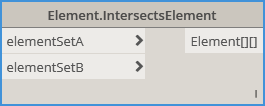
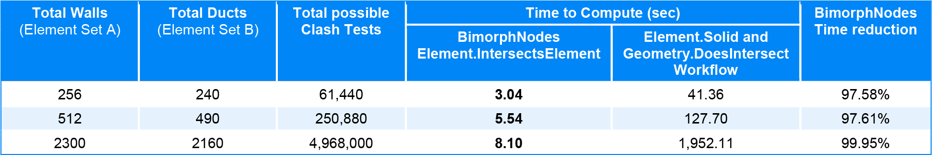
The first of the new clash-detection nodes. It’s now possible to perform ultra-efficient clash-detection in Dynamo using the Element.IntersectsElement node. It utilises a purpose-built Revit API method to perform the intersection test (which itself is optimised) coupled with an optimisation algorithm we’ve developed to filter surrounding elements before performing each clash test, which minimises redundancy. The technique results in a massive performance increase, with up to a 99.95% reduction in overall processing time compared to the same process using Geometry.IntersectAll or Geometry.DoesIntersect + Element.Solid.
The output Elements are structured into sublists to support downstream workflows. Deciphering the output data structure is simple: any elements from Set B that intersect an element in Set A are stored in a sublist (the ‘clash result’). If there are no intersections, an empty sublist is returned to maintain data structure consistency.
The node also includes intelligence which prevents self-intersection if an element is found in both element Set A and B, eliminating false-flags. It means if you only have one element Set but still want the clash results (for example, clashing all pipes against all other pipes), the node can support this workflow without any negative impacts.
Element.IntersectsElement processing speed versus the comparable workflow using OOTB Geometry.DoesIntersect + Element.Solid :
Element.IntersectsSolid
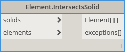
The second of the new clash-detection nodes provides more flexibility and interop with Dynamo Solids. It utilises a purpose-built Revit API method to perform the intersection test which drastically improves efficiency, plus it’s built on the same infrastructure as the Element.IntersectsElement node, meaning its optimised (minimises redundant tests by filtering surrounding elements per clash) and the same logic applies with the output data structure.
Since the use of Dynamo’s Geometry.IntersectAll and Geometry.DoesIntersect method is avoided entirely, opting for a purpose-built method from the Revit API, there are none of the performance bottlenecks typically encountered with these nodes, resulting in a node which yields lightning-fast results despite the fact solid intersections are still being computed.
Element.IntersectsSolid comes into its own if an element isn’t compatible with the Element.IntersectsElement node (see below to learn more) such as Rooms, or for performing clash tests in situations where there is no reference geometry – for example, testing if door swings clash with another element. In this scenario, Dynamo Cylinder extrusions could be created at each door to represent the swing zone, then Element.IntersectsSolid can be used to perform the clash test. The possibilities are endless!
In some cases, solids can fail the intersection process due limitations with certain geometries processed by the Revit API Shape Builder. The node has been designed to handle these failures by returning the indexes of any problem solids to the exceptions[] output, enabling them to be bypassed, or filtered and rerouted to alternative methods.
Element.IntersectsSolid processing speed versus the comparable workflow using OOTB Geometry.DoesIntersect + Element.Solid :

Element.IsCategorySupported
Element.IsElementSupported
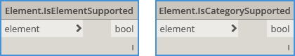
Not all Revit elements or Categories are supported by the two Element.Intersects nodes – either for obvious reasons, or due to limitations in the API – and it’s difficult to tell which since the output from the two Element.Intersects nodes defaults to an empty list where intersections fail. These two nodes provide a means to check if the elements are supported, outputting true or false accordingly. If the element is not supported (such as Rooms), a good alternative is to extract its solid volume and use Element.IntersectsSolid.
Curve.IntersectAll
Intersecting a set of curves to yield a single array of intersection points with no duplicates has, to-date, involved using OOTB Geometry.IntersectAll set to cross-product lacing with Point.PruneDuplicates as shown below:
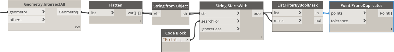
However, the workflow suffers from enormous redundancy primarily due to its reliance upon two computationally expensive nodes. Plus, cross-product lacing is required to perform the brute-force intersection test (all curves intersected against all other curves) adding more profligacy to an already inefficient process. It means that even a small number of curves can take an inordinate amount of time process, and the workflow itself is essentially crippled from the outset.
With the release of BimorphNodes v2.1, the entire workflow is replaced by just one node:
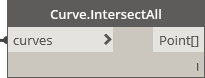
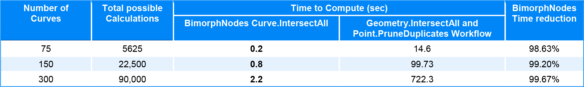
Curve.IntersectAll adds new functionality to Dynamo; the node is ultra-efficient, implementing a purpose-built curve intersection method from the Revit API which is further optimised by our own algorithms to eliminate redundant tests and maximise efficiency. The result is a node which can calculate intersection points infinitely quicker than the same workflow using Geometry.IntersectAll and Point.PruneDuplicates. Here are some performance comparisons:
Curve.SolidIntersection
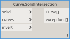
Curve.SolidIntersection node adds entirely new functionality to Dynamo – now solids can be used to intersect or trim curves. Prior to BimorphNodes v2.1 such concepts were not possible, yet this functionality has significant value for a myriad of workflows; from volumetric containment testing to procedural modelling.
The node can output curve segments that either intersect the input solid (default behaviour), or the result can be inverted using the invert switch, which outputs curve segments outside the solid. Inverting essentially creates 2 nodes in 1: Curve.SolidIntersection and a TrimBySolid node!
In some cases, curves can fail the intersection process due to tolerance limitations within the Revit API. The node has been designed to handle these failures by returning the indexes of any problem curves to the exceptions[] output, enabling them to be filtered and rerouted to alternative methods.
BoundingBox.GetElementsInside
BoundingBox.GetElementsIntersect
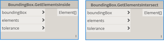
Both nodes filter and return Revit elements either inside or intersecting a bounding box. These nodes expose Revits ElementQuickFilter class, which operate only on the ElementRecord (a low-memory class), making them ideal for rapid element containment testing and collection. Note that the results are – by design – coarse, as the input element Outlines (BoundingBoxes) are used to determine the result, not the geometry. QuickFilters therefore, should be used as a means of optimisation prior to performing more complex, time-consuming processes, such as geometry intersections.
For example, these nodes can be used to optimise an interference checking workflow by collecting only elements within the proximity of another element. The result will be a far more focused collection of elements, making any subsequent geometry or element interference process significantly more efficient as redundant interference tests will be largely eliminated.
The optional tolerance input can be used to collect elements extending from the BoundingBox by the distance input. Use positive values to increase the BoundingBox zone, or negative values to decrease the zone. It uses your active document units (mm, cm, m etc) and converts them to Revit internal units dynamically.
What Else is New?
Firstly, there’s a new node in the BimorphNodes CAD class:
CAD.SymbolicCurvesFormCADLayers
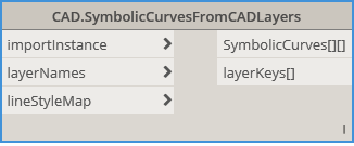
This opens-up new workflows for automated Family creation, enabling users to rapidly convert curves via layer names to symbolic lines, without needing to explode the import. Since its built on the same infrastructure as the other CurveFromCADLayer nodes, line styles can also be mapped during conversion to streamline the entire process.
Next, all the nodes have been improved, providing greater efficiency, better feedback to users if exceptions arise, and bug fixing, with some of the most popular BimorphNodes seeing major feature updates and stability enhancements. Here are a few highlights:
Sheet.Duplicate
New Features:
- Sheet output is BACK: the highly requested Sheet output has been reinstated. You may recall that the Sheet output was removed shortly after Bimorph Nodes v2.0 was released due to certain workflow limitations described here. For v2.1 we’ve developed a new output mechanism to solve these limitations, which returns either:
- Duplicated sheets, or
- Existing sheets (where they match the sheet number of a new duplicate)
- Supports Electric Panel Schedule Views
Fixes:
- The three Area Plan Views types are now fully supported. In previous versions, only GIA plan views would be duplicated. Rentable and Gross Building plan views would be incorrectly reported ‘as existing’ which prevented duplication / placement. The cause of the problem was due to the way Revit distinguishes Area Plan Views using Built-in System Families instead of ViewType; as the node only distinguished views via their ViewType (i.e. AreaPlan) it wasn’t able to comprehend the three types. In v2.1 the problem has been fixed by adopting the same view categorisation as Revit (i.e. System Families for Area Plans)
- Placement of duplicated Parent views (those with dependent views) had a bug in situations where only sheets hosting its dependent views were duplicated. Since the node automatically creates a new Parent view to associate the new duplicated dependent views (to maintain the same view structure), if the sheet hosting the original Parent View was duplicated in a new run (resulting in the duplicated Parent view mentioned), the node would find it in the document and not place it (as it exists). To fix this, new logic has been implemented whenever the problem is encountered which checks if the names match and if the view is a Parent view and can be placed on a sheet. If all conditions return true, the view is assumed to be created from a previous run, and will be placed on the sheet!
Sheet.FromSchedule
New Features:
- Includes a refresh input to get the latest Sheets from the Revit model
- Periodic updating now supported
- New exception handling with descriptive customised warnings to improve usability
Fixes:
- The node was dependent on the Schedule view Sheet Number field having the heading ‘Sheet Number’. If headings were switched off in the Schedule view, or if the field was renamed by the user, or if a language other than English was used, the node would fail (as it wouldn’t be able to find the field). All three issues are now fixed by querying the Schedule view’s SHEET_NUMBER built-in parameter instead.
Schedule.GetTableData
Schedule.GetTableDataColumn
Schedule.GetTableDataRow
New Features:
- All nodes now include a refresh input to get the latest data from the Revit model
- Electric Panel Schedules now supported
- Periodic updating now supported
- New exception handling with descriptive customised warnings to improve usability
Fixes:
- The removeHeadings input failed to check if the headings were visible or not in the Schedule view, resulting in missing output data if they were switched off in Revit. This is now fixed
CAD.CurveFromCADLayers
CAD.DetailCurvesFromCADLayers
New Features:
- Up to 80% performance increase during curve conversion processing
- New exception handling with descriptive customised warnings to improve usability
- Compatible with Revit 2018.1
- All Family Templates Now supported
Fixes:
- Detail Curve creation in Families incorrectly defaulted to Line Style ‘Lines’ instead of the default line style name specific to the Family – now fixed
- If zero-length or near zero-length lines were encountered, an exception would occur which caused the node to prematurely terminate. This is now fixed
Important Considerations Before Upgrading
If you are upgrading from an older version of BimorphNodes, continue reading, otherwise you skip this part.
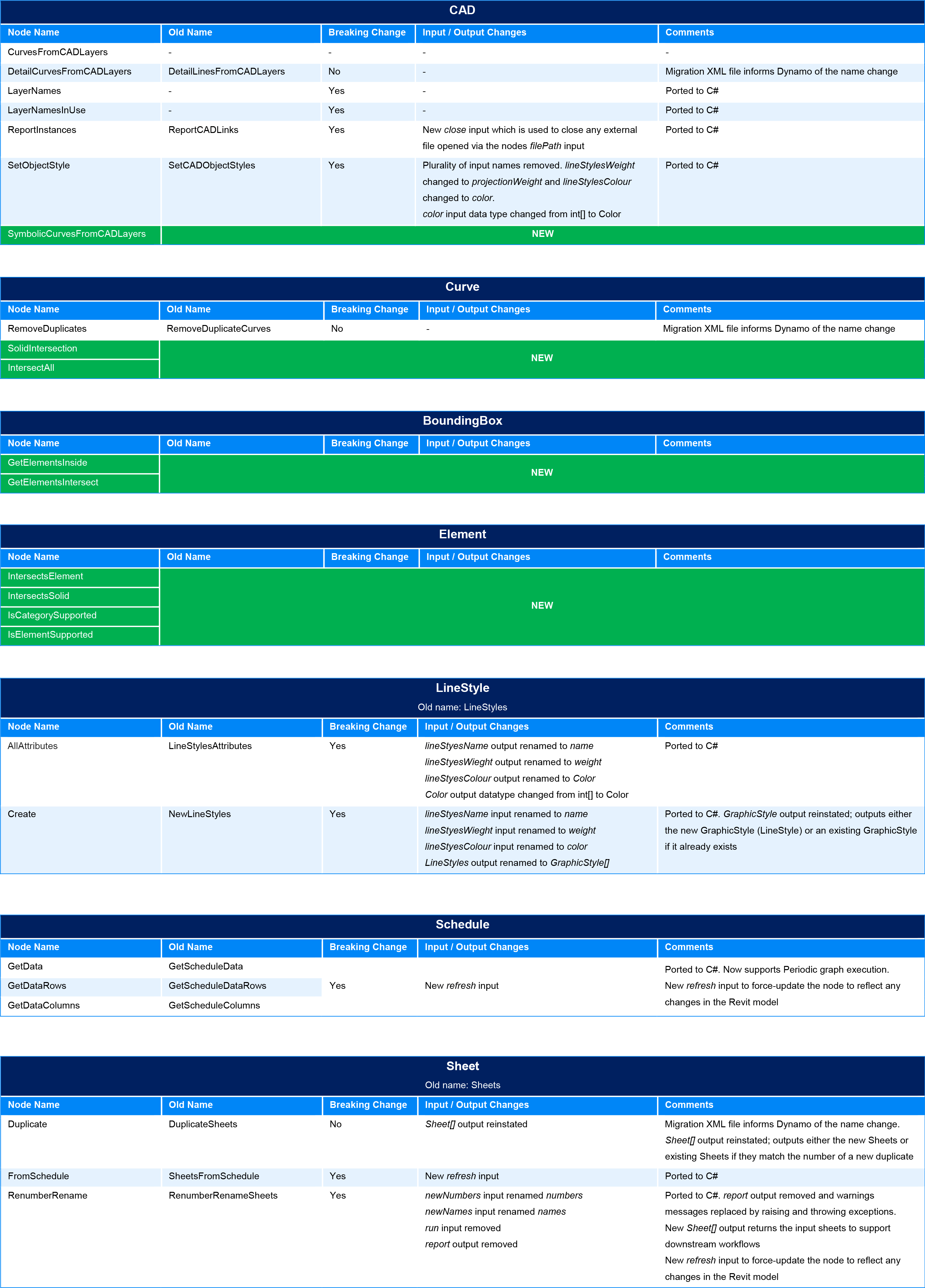
Porting BimorphNodes v2.1 entirely to C# from Python has resulted in breaking changes to most nodes as their GUIDs cant be preserved. If you are upgrading and use older BimorphNodes in your graphs, they will need to manually replaced with the v2.1 versions, so please plan your upgrade strategy carefully to avoid disruption. To aid with the transition, the table below explains what has changed so you can check how the upgrade may affect you:
Why Make Breaking Changes?
Significant changes have been made to BimorphNodes v2.1 for the following reasons:
- To consolidate the codebase into one environment (C#)
- Improve code re-usability and aid with overall code management
- Accelerate the update-cycle, enabling more frequent releases, and to improve overall node reliability/robustness
- Aid development: Bimorph Nodes comprises extensive and relatively complex code which is easier to write, maintain and implement using a strong-typed language (i.e. C#) within an IDE
Upgrading to BimorphNodes v2.1 however, is well worth it:
- Game-changing, ultra-efficient clash-detection and geometry intersection nodes
- Noticeable performance enhancements and greatly improved robustness
- Improved node mark-ups, with more consistent and concise naming which also translates into a more intuitive library structure
- Comprehensive exception handling with customised messages to give better guidance to users if an exception is thrown
- 80% curve conversion speed enhancement to the family of CurvesFromCADLayer nodes
- A collection of highly versatile and unique nodes which are found in no other package
Get Updates and New Content
Don’t forget to check out our BimorphNodes content pages and YouTube channel for user guides and extra content. New video content will be added in due course; be sure to subscribe to get notifications:
BimorphNodes Dictionary: BimorphNodes
YouTube Channel: YouTube
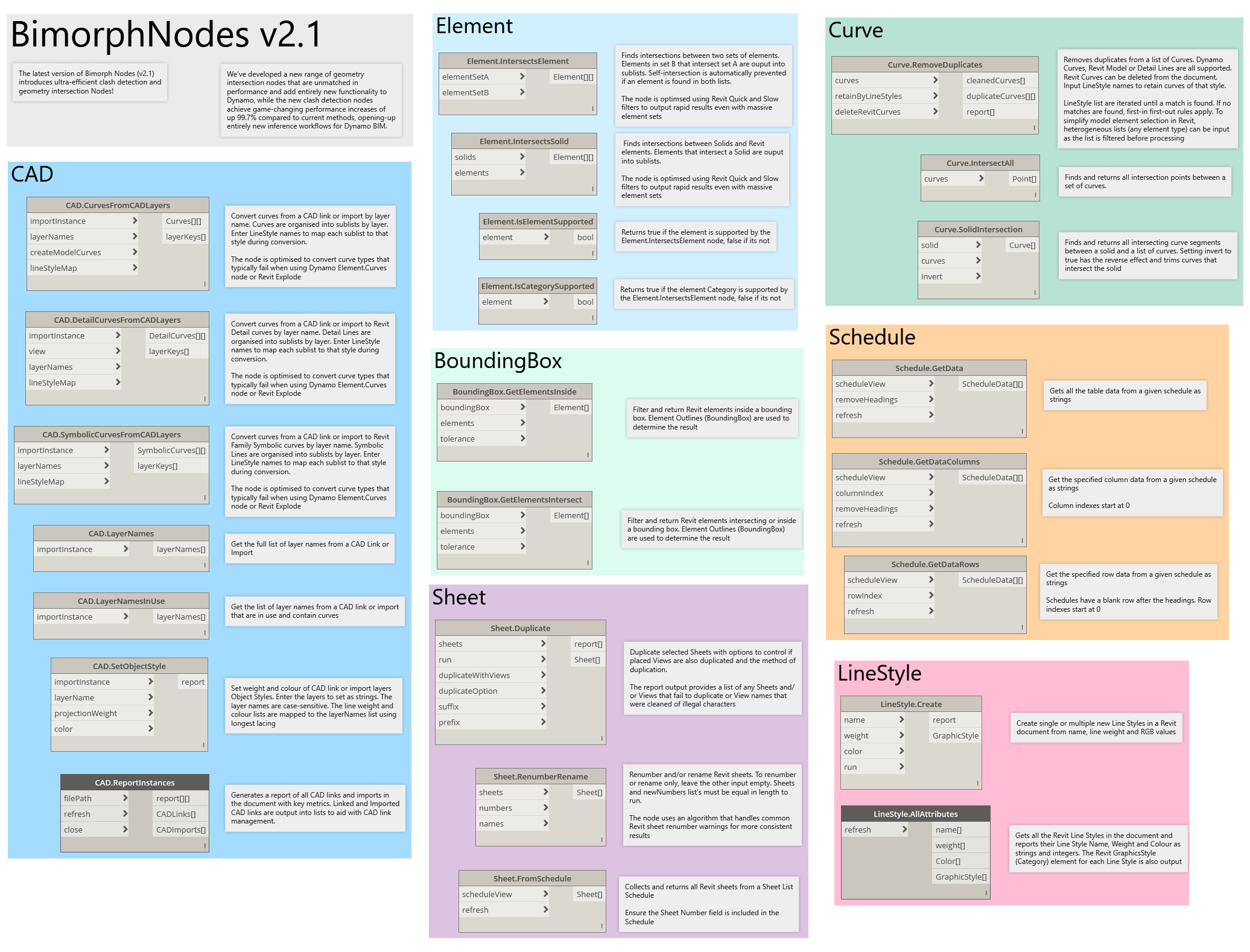
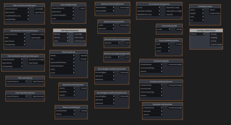
Bimorph Nodes v2.1 Library
Finally, here is the full library of BimorphNodes v2.1: