Workflow: Create Structural Framing Opening for Horizontal Ducts in Revit 2016 using Dynamo 0.9.2

Updated:

Hello folks

It’s been a long time since my last post. Today we will use a new technique to get the intersection polygons between Structural Framing and Ducts in Revit using Dynamo.

This topic has been inspired by Matt Wash and we will use the Location Curve property of Line Based families to get the plane at which the intersection points exist. Then we will use this plane to get the intersection polygon from the Ducts.

As we have the polygons we can pass it to the Python script node to let the magic begin.

create-structural-framing-openings-for-ductwork
The sample Revit project file can be downloaded from here.

The Dynamo workflow can be downloaded from here.

For more free Dynamo tutorials please visit us on Facebook: BIM Oasis

Workflow: Create Rectangular Wall Opening for Horizontal Pipes from a linked file in Revit 2016 using Dynamo 0.9.2

In our previous tutorials we showed how to:
The workflow assumed that the model contains all trades in one file. But most of cases each trade exists in its own file and based on the linking technique used in your firm the relation between the trades projects defers.
In this example I assumed that the architecture linked the piping file to the base model project, because most of cases the architect will be the responsible for making the opening in the walls of his model.
Nothing changed from the Create Rectangular Wall Opening for Horizontal Pipes in Revit 2016 using Dynamo tutorial except the technique of getting the pipe elements. In the previous tutorials we addressing the pipe elements directly from the current model, but now we will access them through the Link file.
The “Get all Pipes from link” Node is pure Python Script that get the link documents from the current project then collect the Pipes Category and set them as its output. The workflow then continues as it is in the Create Rectangular Wall Opening for Horizontal Pipes in Revit 2016 using Dynamo tutorial.
Wall Opening for Pipes - Rectangular - link
The sample Revit project files:
The Dynamo Workflow can be downloaded from here.

Workflow: Create Floor Opening for Vertical Pipes from a linked file in Revit 2016 using Dynamo 0.9.2

In our previous tutorials we showed how to:
The workflow assumed that the model contains all trades in one file. But most of cases each trade exists in its own file and based on the linking technique used in your firm the relation between the trades projects defers.
In this example I assumed that the architecture linked the piping file to the base model project, because most of cases the architect will be the responsible for making the opening in the walls of his model.
Nothing changed from the Create Floor Opening for Vertical Pipes in Revit 2016 using Dynamo tutorial except the technique of getting the pipe elements. In the previous tutorials we addressing the pipe elements directly from the current model, but now we will access them through the Link file.
The “Get all Pipes from link” Node is pure Python Script that get the link documents from the current project then collect the Pipes Category and set them as its output. The workflow then continues as it is in the Create Floor Opening for Vertical Pipes in Revit 2016 using Dynamo tutorial.
Floor Opening for Pipes - link
The sample Revit project files:
The Dynamo Workflow can be downloaded from here.

Create Rectangular Wall Opening for Horizontal Pipes in Revit 2016 using Dynam 0.9.2

First of all thanks for all the fans for the reviews, comments and following up. This topic is prepared as a special request for my followers on LinkedIn, DynamoNodes and Facebook.
In our previous tutorials we showed how to:
In today’s tutorial we will make a little tweak for the Create Wall Opening for Cable Tray in Revit 2016 using Dynamo workflow to perform the rectangular wall opening for horizontal pipes.
The example will use the Revit’s standard rectangular wall opening. Depending on the radius of the pipe the width and height of the opening will be set.
Wall Opening for Pipes - Rectangular
The workflow file can be downloaded from here

Workflow: Create Floor Opening for Vertical Pipes in Revit 2016 using Dynam 0.9.2

As we saw in the previous lessons Create Wall Opening for Cable Tray in Revit 2016 using Dynamo and Create Wall Opening for Ductwork in Revit 2016 using Dynamo it is possible to make opening in Walls for cable trays and ductwork in Revit 2016 using Dynamo.
In today’s lesson we will see how to make openings for Pipes but this time in Floors. All you want to do is to select the Pipes Category and the Floors Category.
Dynamo should determines the intersection surfaces and hence the edges of the surfaces.
We choose in this example to make circular openings.
To control the diameter of the circular opening an offset from the intersection curves shall be done.
Once we determined the radius we can let the Python Script do the rest of the magic.
Create Floor openings for Pipes
You can download the Dynamo workflow from here

Workflow: Create Wall Opening for Cable Tray in Revit 2016 using Dynamo

In the previous lesson Create Wall Opening for Ductwork in Revit 2016 using Dynamo we saw how to create wall openings for ductwork in a project. In today’s lesson we will do the same exercise but this time for cable trays.
First we get all the wall elements and the cable tray elements in the project then get the intersection points between them. As we got the intersection points we need to determine the direction at which the opening shall be placed.
One important point that has bee raised from one of the page’s fans yesterday was that the size of the opening is constant, so now by adjusting the “Size Factor” Node we can control the size of the opening as a function in the dimensions of the cable tray (or duct).
The Revit API and hence Dynamo are using the Feet as its standard measuring units, so in some cases we need to correct the units by multiplying the lengths by conversion factor.
In our case the Revit project units are in mm so I multiplied the lengths came from the Dynamo calculations by 304.8 to convert from Feet to mm.
At the end by using the Python code block we make the magic happen.
Create wall openings for cable tray
You can download the Dynamo workflow from here

Workflow: Create Wall Opening for Ductwork in Revit 2016 using Dynamo

Hi folks!
Have you ever in Revit find it so tedious to track all the clash points between different disciplines and the architecture elements to address them.
Now with Dynamo you can do it so easy. Today’s workflow shows how to find the intersection points between ducts and the walls then using a simple python script we can add the wall opening in the proper position with an arbitrary width and height.
The image of the workflow may not be so clear so I’ll attach the dyn file.
Create wall openings for ductwork
You can download the Dynamo workflow from here

Sheet.ByNameNumberTitleBlockAndView

This standard node enables the automatic creation of Revit Sheets, along with the placement of a view on the newly created sheet. The inputs are:

  • sheetName
  • sheetNumber
  • titleBlockFamilyType
  • view

And the output is the newly created:

  • Sheet

You can find it here in the Library:

bynamenumbertitle

Here is a video of the node in action by Mohamed Mostafa:


Workflow: Building walls from floor edges using Dynamo in Revit 2016

Hello BIM fellows
Today we will see how to quickly create walls from floor edges using Dynamo in Revit 2016. This could be useful for Landscape architects as well as Construction architects.
First we need to get all the Floors that are at the same level, this could be done by getting the intersection set between two lists.
The first list contains all floors in the model and the second one contains all the elements at certain level.
Using combination of “Levels” Node, “Categories” Node and “SetIntesection” Node we get such filtration.
To get the Floor edges we should cut the Floor with a plane and since all floors are almost horizontal we can cut them with the plane of Z axis as its Normal. Once we got the edges the Python Script does its magic.
By using the same Level of the Floors, proper Wall Type and the Floors edges we can so easily draw walls on each edge segment.
Building walls from floor edges
The Dynamo workflow can be downloaded from here

Workflow: Creating free form theater curtain Using Dynamo and Revit 2016

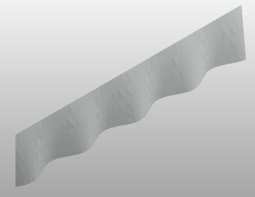
Today we will see how to use the conceptual design in Dynamo to create a Free Form Theater Curtain.
The curtain is a surface which is lofted from several lines. Each line is the connection of two points the one at the bottom and the one at the top.
The points at the bottom are following the Sin wave shape at elevation zero, while the top points are following a straight line at height 1000.
By changing the slider you can control the amplitude of the sin wave hence the deformation of the curtain.
To implement the workflow we need the following Nodes:
  • 4 x Number
  • Range
  • Integer Slider
  • Math.Sin
  • Math.RadiansToDegrees
  • 2 x Points.ByCoordinates
  • Line.ByStartPointEndPoint
  • Surface.ByLoft
  • ImportInstance.ByGeometries

From the the “Range” Node we can get a set of points which will be incorporated to represent the start and end points. As the end points are composing a straight line we will use them as they are. But the start points are composing a Sin wave shaped curve so we need to convert their Y values first to degrees and hence use them as values to the angle input in the “Math.Sin” Node.

Once we got the set of start points and end points we will use the “Line.ByStartPointEndPoints” Node to create the lines which will be used to create the surface.

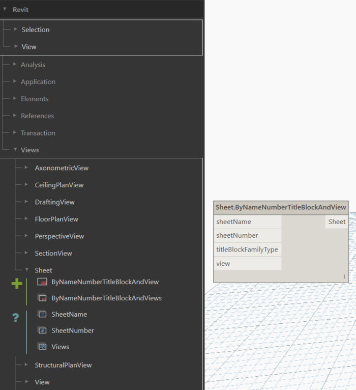
The “Surface.ByLoft” Node will create the surface based on the supplied lines by lofting. Final step is to import the geometry into Revit and this is done by using the “ImportInstance.ByGeometries” Node.Free Form Curtain example

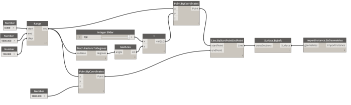
The dynamo workflow can be downloaded from here