Workflow: Manage coordination between spaces and rooms

Original post at: Space-Room coordination

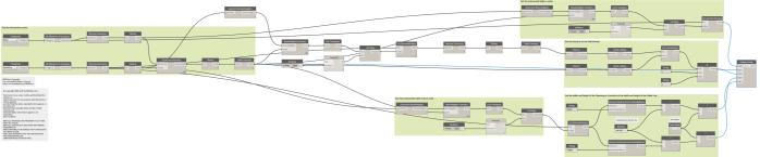
The following workflow uses custom nodes from the packages: “SpringNodes”, “Archi-Lab”, “SteamNodes” and “MEPover”.
There are a few things to consider when managing your spaces:

A: Make sure the levels between the host model and the linked model are aligned;
B: Make sure the levels share the same computation height;
C: Create and coordinate spaces and rooms;
D: Set the limit offset of the spaces.

A. Aligning levels
The first one is easy as this is usually done when setting up your model. I take it everyone knows how to use the copy/monitor function, so let’s skip this step.

B. Set computation heights
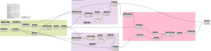
If you only have a few levels in your project it is no problem: just manually check the computation height of the linked levels and the host levels and set the same computation height. However, if there are a lot of levels, Dynamo can come in handy. Here’s a simple workflow for setting the level’s computation height:

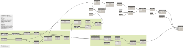
  1. Find the levels from both the host model and the linked architectural model
  2. With a dictionary you can create a list of keys and a list of associated values. In the example above the keys are the elevation values of the levels from the host model and the values are the levels themselves (also from the host model). After that the ‘search keys’ will look up the values associated with those keys.
    The level elevation values from the linked model are used to return the levels from the host model. By using this workflow you will be able to match levels from the linked model to levels in the host model. If however there are levels which can’t find a matching height, then a null value will be returned.
  3. Retrieve the computation height values from the levels in the linked model and use those to set the computation height of the levels in the host model. In this case the SetParameter node gives a warning, because there is a level in the linked model that can’t find a matching level in the host model (like stated in step 2). This doesn’t have to be a problem, just make sure there aren’t any rooms hosted to that level.
    If there are rooms hosted to that level then the next steps will fail as the spaces we are going to generate always need to be associated to a level.

C. Space creation and coordination
This is the hardest part. There is no single right way to manage the coordination between your spaces and the rooms from the linked model. If you are not in the same office as the architect it’s almost impossible to keep track of the changes in the linked model. It would mean checking every space that no longer has a matching room number and looking for that room’s new location or it could also have been deleted altogether.
I therefore put some thought into creating a workflow that would work for any situation, regardless of the changes to the rooms. The only prerequisite for this to work well is that every room has a unique room number (sadly I still run into a lot of architectural models with duplicate room numbers, even though Revit gives explicit warnings stating that this is actually a bad idea…).
let’s assume that every space has the same number as the room it is associated with. Now whenever you load a new architetural model, the spaces will retain their space numbers (basically the state of the old architectural model). All you need to do is find the difference between the new rooms and the existing spaces. There’s basically three options to choose from:
1: A room number has been deleted
2: A room number still exists in the model (and might have moved)
3: A room number is new

To gather the information above we can use a really useful data structure known as a ‘Set’.
Sets are a collection of unique items upon which you can perform some functions you can’t do as efficiently with lists. Luckily Dynamo has included a few nodes for working with sets. There are 2 important methods that can be used with sets: ‘SetDifference’ and ‘SetIntersection’. Explaining these is best done through an example:

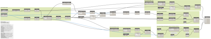
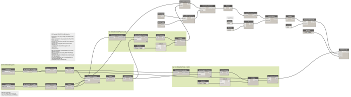
As you can see, this way it’s possible to find out exactly what we are looking for. Now let’s have a look at the next challenge: associating room/space numbers with actual rooms and spaces. We can achieve this by using a dictionary in which the keys are the space/room numbers and the values are the actual spaces/rooms. The output of the dictionaries will be the data to use for creating, managing or deleting the current spaces. Here is the result (with explanation):

  1. First gather the rooms, spaces and their respective numbers.
  2. Use the SetDifference node (room numbers in input 1, space numbers in input 2) in order to have the new room numbers from the linked model returned. Those room numbers are used as input for the dictionary which will return the room elements. Secondly, get those rooms’ locations and use them for the creation of new spaces.
  3. Use the SetDifference node but reverse the input order (space numbers in input 1 and room numbers in input 2). This way the space numbers for which there is no longer a room number available in the linked model are returned. With the dictionary the space elements are returned. All that’s left is to simply delete these spaces.
  4. Find out which rooms and spaces with the same numbers are still in both the models, using the SetIntersection node. With the dictionary we retrieve the space elements. Because this doesn’t tell us whether the rooms and spaces are still in the same location, we need to check their locations and then move the spaces if necessary. Sadly Dynamo doesn’t allow moving spaces to different levels with any of the normal nodes. For this reason I created the node: “Space coordination move to associated room”. This node will find the room in the linked document with the same room number as the space. It will check its location and if that location isn’t the same as the space it will attempt to move the spaces to rooms with the same numbers.

After this make sure that the new space numbers change to match the associated room numbers. After that you can repeat this entire workflow for every new linked model update you receive.

Workflow: Create Structural Framing Opening for Horizontal Ducts from a linked file in Revit 2016 using Dynamo 0.9.2

In our previous tutorial Create Structural Framing Opening for Horizontal Ducts in Revit 2016 using Dynamo 0.9.2 we saw how to create openings for ductwork in structural framing which coexist in the same file.
In today’s tutorial I have created another workflow and I will show how to create the openings but with the ductwork file inserted in the structure file as a link.
First we will use the Python Script node to get all the ducts elements from the link then we will pass those elements to the “Geometry.Intersects” Node. The intersection between two geometries is another geometry so we need to allocate the center of the intersection geometry thus we use the “Solid.Centroid” Node.
After we will got the intersection points we shall identify the duct and the beam that create each successful intersection.
Once we have the beam corresponding to each duct we will use a plane that is parallel to the beam and centered in the intersection point to get the boundaries of the intersection by get the intersection between the plane and the duct. As now we have the boundaries we can create the opening from them.
create-structural-framing-openings-for-ductwork-link
The Dynamo workflow file can be downloaded from here.
The sample Revit files can be downloaded from the following links:

Workflow: Create Structural Framing Opening for Horizontal Ducts in Revit 2016 using Dynamo 0.9.2

Updated:

Hello folks

It’s been a long time since my last post. Today we will use a new technique to get the intersection polygons between Structural Framing and Ducts in Revit using Dynamo.

This topic has been inspired by Matt Wash and we will use the Location Curve property of Line Based families to get the plane at which the intersection points exist. Then we will use this plane to get the intersection polygon from the Ducts.

As we have the polygons we can pass it to the Python script node to let the magic begin.

create-structural-framing-openings-for-ductwork
The sample Revit project file can be downloaded from here.

The Dynamo workflow can be downloaded from here.

For more free Dynamo tutorials please visit us on Facebook: BIM Oasis

Workflow: Import Geometry to Dynamo from CAD Link

I had a simple question recently: How do I get some DWG or DXF geometry into Dynamo to do some simple tasks, like placing families at points in Revit?

I looked for the DWG import nodes, until I realised they only come with Dynamo Studio. Then I realised that Dynamo Studio doesn’t run on top of Revit. Weird, huh?

Then, I came across this little offhand comment from John Pierson:
You can import in Revit> select file> and query geometry.

It can’t be that easy, can it? Yes, it can!

Just like this:

So, by simple selecting the Link or Import element in Revit, we can use Element.Geometry to unpack its geometry. This method would likely work with any other CAD format that Revit can Link or Import, such as SAT, SKP or DGN.

I had tried some more challenging workarounds like going via Flux, but sometimes the easiest option is the best.

Workflow: Create Rectangular Wall Opening for Horizontal Pipes from a linked file in Revit 2016 using Dynamo 0.9.2

In our previous tutorials we showed how to:
The workflow assumed that the model contains all trades in one file. But most of cases each trade exists in its own file and based on the linking technique used in your firm the relation between the trades projects defers.
In this example I assumed that the architecture linked the piping file to the base model project, because most of cases the architect will be the responsible for making the opening in the walls of his model.
Nothing changed from the Create Rectangular Wall Opening for Horizontal Pipes in Revit 2016 using Dynamo tutorial except the technique of getting the pipe elements. In the previous tutorials we addressing the pipe elements directly from the current model, but now we will access them through the Link file.
The “Get all Pipes from link” Node is pure Python Script that get the link documents from the current project then collect the Pipes Category and set them as its output. The workflow then continues as it is in the Create Rectangular Wall Opening for Horizontal Pipes in Revit 2016 using Dynamo tutorial.
Wall Opening for Pipes - Rectangular - link
The sample Revit project files:
The Dynamo Workflow can be downloaded from here.

Workflow: Create Floor Opening for Vertical Pipes from a linked file in Revit 2016 using Dynamo 0.9.2

In our previous tutorials we showed how to:
The workflow assumed that the model contains all trades in one file. But most of cases each trade exists in its own file and based on the linking technique used in your firm the relation between the trades projects defers.
In this example I assumed that the architecture linked the piping file to the base model project, because most of cases the architect will be the responsible for making the opening in the walls of his model.
Nothing changed from the Create Floor Opening for Vertical Pipes in Revit 2016 using Dynamo tutorial except the technique of getting the pipe elements. In the previous tutorials we addressing the pipe elements directly from the current model, but now we will access them through the Link file.
The “Get all Pipes from link” Node is pure Python Script that get the link documents from the current project then collect the Pipes Category and set them as its output. The workflow then continues as it is in the Create Floor Opening for Vertical Pipes in Revit 2016 using Dynamo tutorial.
Floor Opening for Pipes - link
The sample Revit project files:
The Dynamo Workflow can be downloaded from here.

Create Rectangular Wall Opening for Horizontal Pipes in Revit 2016 using Dynam 0.9.2

First of all thanks for all the fans for the reviews, comments and following up. This topic is prepared as a special request for my followers on LinkedIn, DynamoNodes and Facebook.
In our previous tutorials we showed how to:
In today’s tutorial we will make a little tweak for the Create Wall Opening for Cable Tray in Revit 2016 using Dynamo workflow to perform the rectangular wall opening for horizontal pipes.
The example will use the Revit’s standard rectangular wall opening. Depending on the radius of the pipe the width and height of the opening will be set.
Wall Opening for Pipes - Rectangular
The workflow file can be downloaded from here

Workflow: Create Floor Opening for Vertical Pipes in Revit 2016 using Dynam 0.9.2

As we saw in the previous lessons Create Wall Opening for Cable Tray in Revit 2016 using Dynamo and Create Wall Opening for Ductwork in Revit 2016 using Dynamo it is possible to make opening in Walls for cable trays and ductwork in Revit 2016 using Dynamo.
In today’s lesson we will see how to make openings for Pipes but this time in Floors. All you want to do is to select the Pipes Category and the Floors Category.
Dynamo should determines the intersection surfaces and hence the edges of the surfaces.
We choose in this example to make circular openings.
To control the diameter of the circular opening an offset from the intersection curves shall be done.
Once we determined the radius we can let the Python Script do the rest of the magic.
Create Floor openings for Pipes
You can download the Dynamo workflow from here

Workflow: Create Wall Opening for Cable Tray in Revit 2016 using Dynamo

In the previous lesson Create Wall Opening for Ductwork in Revit 2016 using Dynamo we saw how to create wall openings for ductwork in a project. In today’s lesson we will do the same exercise but this time for cable trays.
First we get all the wall elements and the cable tray elements in the project then get the intersection points between them. As we got the intersection points we need to determine the direction at which the opening shall be placed.
One important point that has bee raised from one of the page’s fans yesterday was that the size of the opening is constant, so now by adjusting the “Size Factor” Node we can control the size of the opening as a function in the dimensions of the cable tray (or duct).
The Revit API and hence Dynamo are using the Feet as its standard measuring units, so in some cases we need to correct the units by multiplying the lengths by conversion factor.
In our case the Revit project units are in mm so I multiplied the lengths came from the Dynamo calculations by 304.8 to convert from Feet to mm.
At the end by using the Python code block we make the magic happen.
Create wall openings for cable tray
You can download the Dynamo workflow from here

Workflow: Building walls from floor edges using Dynamo in Revit 2016

Hello BIM fellows
Today we will see how to quickly create walls from floor edges using Dynamo in Revit 2016. This could be useful for Landscape architects as well as Construction architects.
First we need to get all the Floors that are at the same level, this could be done by getting the intersection set between two lists.
The first list contains all floors in the model and the second one contains all the elements at certain level.
Using combination of “Levels” Node, “Categories” Node and “SetIntesection” Node we get such filtration.
To get the Floor edges we should cut the Floor with a plane and since all floors are almost horizontal we can cut them with the plane of Z axis as its Normal. Once we got the edges the Python Script does its magic.
By using the same Level of the Floors, proper Wall Type and the Floors edges we can so easily draw walls on each edge segment.
Building walls from floor edges
The Dynamo workflow can be downloaded from here