Space number to duct network concatenate

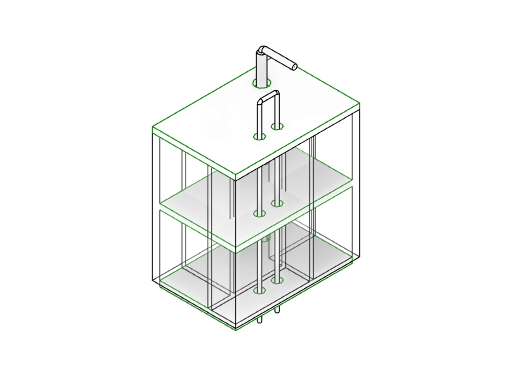
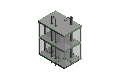
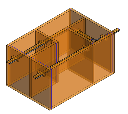
Revit has a built in function that can let you know in which space an air terminal is located. Rhythm has a great node: ‘Element.Space’ for this. Unfortunately most other elements that you’d like associated with a space don’t have access to this space information. The node ‘Space number to network concatenate’ can assign the air terminal’s space number to every upstream element in the connected duct network. While traversing it will concatenate every space number into the parameter with a comma.

The node will stop traversing once it can no longer find an opposing flow direction, encounters a different system classification, encounters an element it has already encountered (and thus has entered some kind of loop) or there is nothing connected to the current element.

space-number-to-duct-network-concat

Inputs:

  • Air terminal: the starting air terminals from where the traversal into the duct network will start.
  • ParameterName: the parameter of the elements in the duct network to which the space numbers will be written to.
  • Category: only elements of these categories will have their parameter written to. Supports multiple categories.
  • SizeLimitFactor: an optional input that controls how far into the network the parameters will be written. The node will stop when the element’s size in the network is ‘factor’ times as big as the starting size. The default is set to 20.

Output:

  • The input elements are returned unless the air terminal is not located in a space, in which case a string indicating no space is found is returned.

The node can be found in the MEPover package version 2017.2.13 and up.

Workflow: Create Structural Framing Opening for Horizontal Ducts from a linked file in Revit 2016 using Dynamo 0.9.2

In our previous tutorial Create Structural Framing Opening for Horizontal Ducts in Revit 2016 using Dynamo 0.9.2 we saw how to create openings for ductwork in structural framing which coexist in the same file.
In today’s tutorial I have created another workflow and I will show how to create the openings but with the ductwork file inserted in the structure file as a link.
First we will use the Python Script node to get all the ducts elements from the link then we will pass those elements to the “Geometry.Intersects” Node. The intersection between two geometries is another geometry so we need to allocate the center of the intersection geometry thus we use the “Solid.Centroid” Node.
After we will got the intersection points we shall identify the duct and the beam that create each successful intersection.
Once we have the beam corresponding to each duct we will use a plane that is parallel to the beam and centered in the intersection point to get the boundaries of the intersection by get the intersection between the plane and the duct. As now we have the boundaries we can create the opening from them.
create-structural-framing-openings-for-ductwork-link
The Dynamo workflow file can be downloaded from here.
The sample Revit files can be downloaded from the following links:

Workflow: Create Structural Framing Opening for Horizontal Ducts in Revit 2016 using Dynamo 0.9.2

Updated:

Hello folks

It’s been a long time since my last post. Today we will use a new technique to get the intersection polygons between Structural Framing and Ducts in Revit using Dynamo.

This topic has been inspired by Matt Wash and we will use the Location Curve property of Line Based families to get the plane at which the intersection points exist. Then we will use this plane to get the intersection polygon from the Ducts.

As we have the polygons we can pass it to the Python script node to let the magic begin.

create-structural-framing-openings-for-ductwork
The sample Revit project file can be downloaded from here.

The Dynamo workflow can be downloaded from here.

For more free Dynamo tutorials please visit us on Facebook: BIM Oasis

Read From IFC

I found some Python IFC schema reading code and adapted it for use in Dynamo. It took a bit of work and isn’t perfect yet, but basically it just takes a path to an IFC file, and a schema definition, and attempts to unpack the information from the IFC file into lists.

The original code was set up to search by dictionary method (which would be faster), but I kept hitting some errors because the schema defines more attributes than are typically defined by a Revit IFC export. I have output these attribute discrepancies in the ‘attribute read status output’. In the end I made some ‘long lists’ which could be queried in various ways.

So the outputs are:

  • log – a log of the reading of the schema and the IFC file
  • attribute read status – comparison between schema and actual attributes in the IFC file
  • line Ids – the id of the line from the IFC text data
  • IFC name – the name of the line from the IFC text data
  • attributesFromSchema – the official attributes defined for that IFC name
  • attribute values – values from the line, as searched by the attributesFromSchema

Here are the basic outputs:


Logging:

logs

As the main lists are all matched with the amount of lines in the IFC, you can then do filtering and other operations:


I was also looking at making a Dynamo to BimServer connector, possibly adapting this code: https://github.com/aothms/python-bimserver-client(but I didn’t do that yet 🙂

This node will be available in Bakery package, in the IFC group.

Workflow: Create Rectangular Wall Opening for Horizontal Pipes from a linked file in Revit 2016 using Dynamo 0.9.2

In our previous tutorials we showed how to:
The workflow assumed that the model contains all trades in one file. But most of cases each trade exists in its own file and based on the linking technique used in your firm the relation between the trades projects defers.
In this example I assumed that the architecture linked the piping file to the base model project, because most of cases the architect will be the responsible for making the opening in the walls of his model.
Nothing changed from the Create Rectangular Wall Opening for Horizontal Pipes in Revit 2016 using Dynamo tutorial except the technique of getting the pipe elements. In the previous tutorials we addressing the pipe elements directly from the current model, but now we will access them through the Link file.
The “Get all Pipes from link” Node is pure Python Script that get the link documents from the current project then collect the Pipes Category and set them as its output. The workflow then continues as it is in the Create Rectangular Wall Opening for Horizontal Pipes in Revit 2016 using Dynamo tutorial.
Wall Opening for Pipes - Rectangular - link
The sample Revit project files:
The Dynamo Workflow can be downloaded from here.

Workflow: Create Floor Opening for Vertical Pipes from a linked file in Revit 2016 using Dynamo 0.9.2

In our previous tutorials we showed how to:
The workflow assumed that the model contains all trades in one file. But most of cases each trade exists in its own file and based on the linking technique used in your firm the relation between the trades projects defers.
In this example I assumed that the architecture linked the piping file to the base model project, because most of cases the architect will be the responsible for making the opening in the walls of his model.
Nothing changed from the Create Floor Opening for Vertical Pipes in Revit 2016 using Dynamo tutorial except the technique of getting the pipe elements. In the previous tutorials we addressing the pipe elements directly from the current model, but now we will access them through the Link file.
The “Get all Pipes from link” Node is pure Python Script that get the link documents from the current project then collect the Pipes Category and set them as its output. The workflow then continues as it is in the Create Floor Opening for Vertical Pipes in Revit 2016 using Dynamo tutorial.
Floor Opening for Pipes - link
The sample Revit project files:
The Dynamo Workflow can be downloaded from here.

Create Rectangular Wall Opening for Horizontal Pipes in Revit 2016 using Dynam 0.9.2

First of all thanks for all the fans for the reviews, comments and following up. This topic is prepared as a special request for my followers on LinkedIn, DynamoNodes and Facebook.
In our previous tutorials we showed how to:
In today’s tutorial we will make a little tweak for the Create Wall Opening for Cable Tray in Revit 2016 using Dynamo workflow to perform the rectangular wall opening for horizontal pipes.
The example will use the Revit’s standard rectangular wall opening. Depending on the radius of the pipe the width and height of the opening will be set.
Wall Opening for Pipes - Rectangular
The workflow file can be downloaded from here

Workflow: Create Floor Opening for Vertical Pipes in Revit 2016 using Dynam 0.9.2

As we saw in the previous lessons Create Wall Opening for Cable Tray in Revit 2016 using Dynamo and Create Wall Opening for Ductwork in Revit 2016 using Dynamo it is possible to make opening in Walls for cable trays and ductwork in Revit 2016 using Dynamo.
In today’s lesson we will see how to make openings for Pipes but this time in Floors. All you want to do is to select the Pipes Category and the Floors Category.
Dynamo should determines the intersection surfaces and hence the edges of the surfaces.
We choose in this example to make circular openings.
To control the diameter of the circular opening an offset from the intersection curves shall be done.
Once we determined the radius we can let the Python Script do the rest of the magic.
Create Floor openings for Pipes
You can download the Dynamo workflow from here

Workflow: Create Wall Opening for Cable Tray in Revit 2016 using Dynamo

In the previous lesson Create Wall Opening for Ductwork in Revit 2016 using Dynamo we saw how to create wall openings for ductwork in a project. In today’s lesson we will do the same exercise but this time for cable trays.
First we get all the wall elements and the cable tray elements in the project then get the intersection points between them. As we got the intersection points we need to determine the direction at which the opening shall be placed.
One important point that has bee raised from one of the page’s fans yesterday was that the size of the opening is constant, so now by adjusting the “Size Factor” Node we can control the size of the opening as a function in the dimensions of the cable tray (or duct).
The Revit API and hence Dynamo are using the Feet as its standard measuring units, so in some cases we need to correct the units by multiplying the lengths by conversion factor.
In our case the Revit project units are in mm so I multiplied the lengths came from the Dynamo calculations by 304.8 to convert from Feet to mm.
At the end by using the Python code block we make the magic happen.
Create wall openings for cable tray
You can download the Dynamo workflow from here

Workflow: Create Wall Opening for Ductwork in Revit 2016 using Dynamo

Hi folks!
Have you ever in Revit find it so tedious to track all the clash points between different disciplines and the architecture elements to address them.
Now with Dynamo you can do it so easy. Today’s workflow shows how to find the intersection points between ducts and the walls then using a simple python script we can add the wall opening in the proper position with an arbitrary width and height.
The image of the workflow may not be so clear so I’ll attach the dyn file.
Create wall openings for ductwork
You can download the Dynamo workflow from here