In the second part of the “Family Distribution” lesson we will use the Family “Chair” and distribute it on a closed path around a Table.
In the part 1 of this lesson we allowed Dynamo to calculate automatically the length of each segment by dividing the total length of the path by the number of segments. This time we will do the opposite, we will specify the segment length and let Dynamo calculate the number of segments needed.
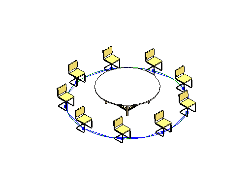
For this part of the lesson we will draw a Model Curve on the shape of a circle to use it as a guide for the distribution path, divide it into equally spaced segments then insert the “Chair” Family at the end point of each segment. We will let the “Table” Family be at the center of the circle.
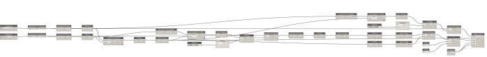
So as we planned the workflow logic in our mind we can find the nodes that are needed to implement it. Now we will open Dynamo and create a new Workspace.
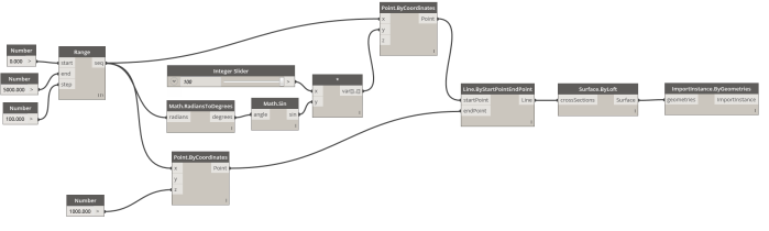
From the Categories Search find the following nodes:
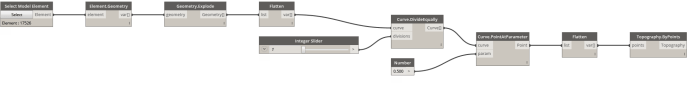
- Select model element
- Element.Curves
- Curve.DivideByDistance
- Number Slider
- Curve.EndPoint
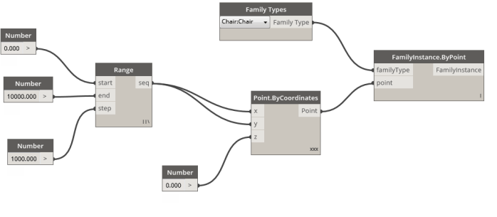
- Family Types
- FamilyInstance.ByPoint
In order to insert a model element from Revit environment into Dynamo environment we shall use the ”Select model element” Node, so click on select and from Revit project pick the model line.
After the Model Curve is brought into Dynamo we need to extract the Curve geometry from it so we connect the ”Select model element” Node output to the “Element.Curves” Node input. The curve geometry is ready now to be divided so we will connect the output of the “Element.Curves” Node to the input of the “Curve.Divide Equally” Node input.
To determine the length of each segment we will connect the “Number Slider” Node to the “divisions” input in the “Curve. DivideByDistance” Node. By changing the slider value the number of divisions will increase or decrease respectively.
As the curve has been segmented we need to locate the end points as they will be our insertion positions for the “Chair” Family instances. So connect the output of the “Curve. DivideByDistance” Node to the “Curve.EndPoint” Node input. Now from the “Family Types” Node select the “Chair” Family Type and connect it to the “FamilyInstance.ByPoint” Node.
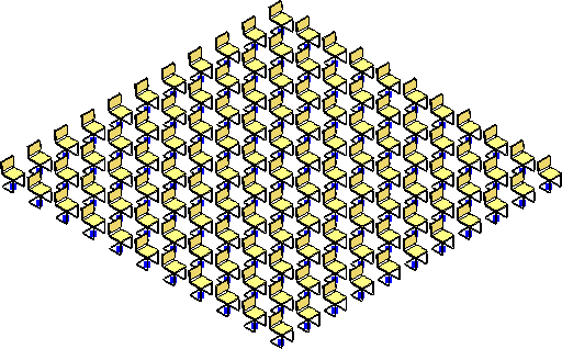
The last step before hitting the “Run” button is to connect the insertion points coming from the “Curve.EndPoint” Node into the “FamilyInstance.ByPoint” Node. We can hit “Run” button and see the result in the Revit view. If we set the run mode in Dynamo to automatic then we can change the number of inserted instances based on the length of segments by changing the value of the Number Slider online.
 The Dynamo Workflow can be downloaded from here